Concrete Pipe Structural Design Calculator
The MPA Precast pipe structural design calculator simplifies concrete pipeline design calculations based on the recommendations in BS 9295 Guide to the structural design of buried pipelines. The Structural design calculator offers all the basic values; from external design loads (We), to bedding factors (Fm) taking into account the pipe crushing strength (Fn). It then offers advice on what type of bedding to use. The calculated load (We), which is the total load a concrete pipe in a trench is required to sustain, is used in the design formula as follows:
Test strength of pipe (Fn): The Structural design calculator test strength of a concrete pipe may be referred to as Fc or Fn Values are specified in BS 5911- Part 1: 2021 for a Class 120 pipe being the single strength class used in the UK. For a reinforced concrete pipe Fc is the load which the pipe will sustain without developing a crack exceeding 0.30mm in width over a length of 300mm and Fn is the load which the pipe will sustain without collapse, irrespective of crack width. However, to further simplify the procedure it is more straightforward to use the maximum test load Fn and apply a factor of safety (Fse) of 1.5 for reinforced pipes.
Safety (Fse): These are taken to be Fse = 1.5 for reinforced pipes and Fse = 1.25 for unreinforced pipes. Pipe with diameter ranges between DN300 to DN600 are always unreinforced. In the pipe size range ≥ DN675 some manufacturers make unreinforced pipes. Designers and specifiers should check availability with the pipe manufacturers.
Design Load (We): BS9295:2020 recommends the method for calculating We. Additionally the MPA Precast Technical Guide provides tables to obtain the loads for determining We.
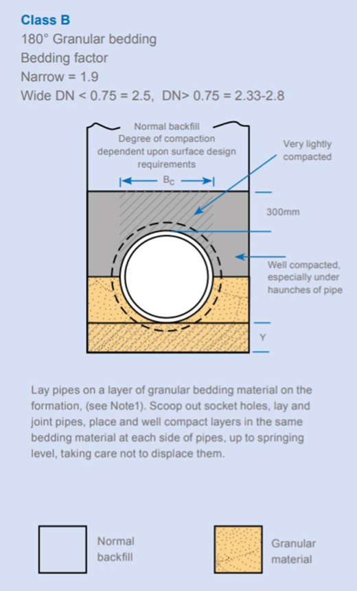
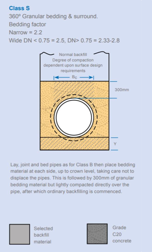
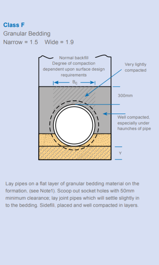
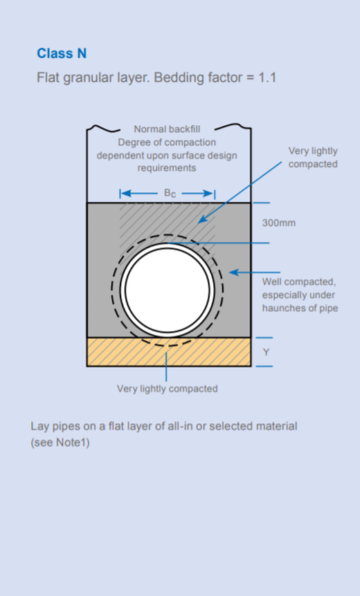
Bedding Factor (Fm): The bedding class to be used will depend on the bedding factor (Fm) calculated. BS9295:2020 gives details of the available bedding classes required to meet the Fm. Bedding classes N and F provide bedding factors of 1.1 and 1.5 respectively. However they are not commonly used in the UK and care should be taken to ensure satisfactory compaction around the pipe is achieved so no settlement occurs. Predominantly in the UK bedding classes B and S are used providing bedding factors of 1.9 and up to 2.8. For higher loads a Class A bedding can be used being a concrete cradle.
Click on illustrations to enlarge
 |
 |
 |
 |
Using the Structural Design Calculator:
The Structural Design Calculator (below) incorporates different values for We and Fn depending on the type of pipe, cover depth, and activity above ground. The Structural Design Calculator also carries out the basic calculations associated with the formulae above.To use the calculator you will need to input the following information, some fields are automatically generated:
| Project / pipeline ref | User input |
| Nominal diameter (DN) of the pipe | User via drop down |
| Pipeline outside diameter | Default automatically generated |
| Installation condition | User via drop down |
| Maximum trench width | Default for narrow trench automatically generated but can be overwritten with required width |
| Cover depth of pipe installed (in metres) | User input |
| Factor of Safety Fse = 1.25 for unreinforced pipes DN225-600mm; 1.5 for reinforced pipes DN675-2400mm | User via drop down |
| Vehicle surcharge | User via drop down |
The Structural Design Calculator will then recommend the acceptable bedding class(es) available.
Classes N and F are not included in the calculator however it calculates the bedding factor required and they may be considered if the Fm value is satisfactory for the bedding class and the designer has considered the limitations of class N and F beddings
Where very high loads are generated, a Class A bedding may be required. A bespoke calculation is generally required and reference to BS 9295:2020 Table 5 and Annex A.14 should be considered due to the range of bedding factors for a Class A ( 2.6-4.8)
Reference should be made to BS 9295:2020 for advice on the installation condition as the designer is required to have control over the trench width for a narrow trench design and or specify the maximum permitted trench width.
Pipes at cover depths under 0.9 metres or over 8 metres may need special consideration and are not accounted for in this calculator. Please contact MPA Precast for advice
Results
Design Data
| Project Ref | ||
| Pipe Diameter (m) | ||
| Pipe Outside Diameter (m) | ||
| Installation condition (trench type) | ||
| Maximum Trench width | For Narrow Trench conditions | |
| Cover Depth (m) | ||
| Fse | ||
| Vehicle Surcharge Type |
Results
| Total External Load We | kN/m | |
| Bedding Factor required Fm | Eq (10) | |
| Provide bedding Class | Tables 5 & 6 | |
| Bedding Factor provided |
Export these results to a PDF
Note: Caution should be exercised when installing a pipe using Classes F or N. The contractor will need to ensure that the ground is adequately stable to support a Class F or N pipeline bedding
Whilst every care is taken to ensure the accuracy of the "Structural Design Calculator", MPA Precast cannot accept any liability arising from its use. It is offered as a guide, and not a substitute for the services of a suitably qualified engineer.